
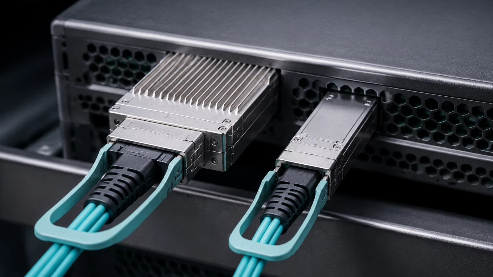
An "800G OSFP" description does not by itself prove that two devices can form an 800G link. In NVIDIA networking, a twin-port OSFP switch cage may carry two independent 400Gb/s ports, while an adapter-side OSFP or QSFP112 cage may carry one 400Gb/s port. Compatibility requires the host cages, electrical lane mapping, modulation, protocol, cable or optical reach, fiber connector, and breakout mode to agree at both ends.
This distinction matters because NVIDIA 400G and 800G interconnects are often described by catalog labels rather than complete link definitions. A cable can have the correct outer connector and still be wrong for the switch port, adapter, or intended split. The reliable purchasing unit is not "one 800G cable." It is a documented link from a specific source port to a specific destination port using a qualified interconnect part number.
Understand what the speed describes
NVIDIA's current LinkX portfolio groups 800Gb/s and 400Gb/s interconnects together in the 100G-PAM4 OSFP product line. Quantum-2 InfiniBand and Spectrum-4 SN5600 Ethernet switches use twin-port OSFP connectors. A single physical switch cage can therefore expose two 400G network ports. The combined electrical capacity is 800G, but each logical network link remains 400G.
At the endpoint, ConnectX-7 uses OSFP or QSFP112 depending on the adapter, while BlueField-3 uses QSFP112. This creates several valid cable arrangements: twin-port OSFP to two endpoint connectors, single-port OSFP to an adapter OSFP, or optical assemblies built around the required lane and fiber mapping. These arrangements are not interchangeable without checking the exact product documentation.
| Interconnect family | Typical role | Key compatibility boundary |
|---|---|---|
| 400G / 800G OSFP, 100G-PAM4 | Quantum-2 and Spectrum-4 SN5600 switch links to ConnectX-7, BlueField-3, DGX systems, or other switches | Switch-side twin-port OSFP lane mapping must match a single-port or split endpoint arrangement |
| 400G QSFP-DD, 50G-PAM4 | Ethernet links involving Spectrum SN5400 or SN4000 generations and supported endpoints | Ethernet-only product family; modulation and endpoint cage differ from 100G-PAM4 400G links |
| 400G QSFP112, 100G-PAM4 | Single 400G endpoint port on supported ConnectX-7 or BlueField-3 configurations | Four 100G electrical lanes; a switch-side twin-port OSFP cable must map to the correct half |
| 200G QSFP56, 50G-PAM4 | HDR InfiniBand and 200GbE links | Different per-lane rate and generation; do not infer compatibility from the QSFP shape alone |
| 100G QSFP28, 25G-NRZ | EDR InfiniBand and 100GbE links | Legacy lane rate and reach options; requires a supported 100G host mode or breakout path |
OSFP and QSFP112 are not mechanically interchangeable
OSFP is physically larger and can provide eight high-speed electrical lanes. QSFP112 uses four lanes at 100G per lane for a 400G port. The different cage size is visible, but the more important difference is how the switch and endpoint assign those lanes.
A passive mechanical conversion is not a general solution. The cable assembly or optical system must implement a lane arrangement supported by both devices. When a twin-port switch OSFP is split toward two adapters, each branch must land on the intended 400G port and the switch configuration must expose the corresponding logical ports. Always retain the port map with the cable schedule.
Protocol support must be stated explicitly
The NVIDIA 100G-PAM4 OSFP portfolio includes InfiniBand and Ethernet connectivity, but that does not mean every part number supports both protocols in every host. The 400G QSFP-DD 50G-PAM4 portfolio described by NVIDIA is Ethernet only. A product selected for a Spectrum Ethernet link should not be assumed to operate in a Quantum InfiniBand fabric merely because both links are called 400G.
Write "NDR 400G InfiniBand" or "400GbE" in the link specification. Add the switch and adapter model, firmware context, and connector at each end. This removes ambiguity before anyone compares price or lead time.
Choose copper, active cable, or optics by the physical route
For the current 400G/800G 100G-PAM4 portfolio, NVIDIA lists direct-attach copper up to 3 meters, linear active copper from 3 to 5 meters, multimode optics to 50 meters, and single-mode options at longer reaches including 100 meters, 500 meters, and 2 kilometers. These are portfolio ranges. The reach, bend radius, cable diameter, power, and environmental limits of the selected part number still govern the installation.
| Medium | Where it is useful | What to verify |
|---|---|---|
| Passive DAC | Short, predictable in-rack paths with low interconnect power | Maximum qualified length, cable bulk, bend radius, airflow, host equalization, and exact end types |
| Active copper / linear active copper | Longer copper reaches where passive loss is too high | Power, thermal behavior, supported host combinations, and whether the assembly is protocol-specific |
| AOC | Lightweight rack-to-rack runs where fixed optical ends are acceptable | End type, length, serviceability, pulling method, and replacement strategy |
| Pluggable optics plus fiber | Structured cabling, longer reach, or routes requiring replaceable modules | Wavelength, fiber type, MPO or LC connector, polarity, optical budget, module pairing, and cleanliness |
Do not select the medium from straight-line rack distance. Measure the routed length through vertical and horizontal managers, allow for service loops without violating bend radius, and check whether a thick copper assembly obstructs adjacent ports or airflow.
Fiber connector and polarity errors can survive a visual inspection
Current multimode 400G links may use MPO-12/APC assemblies, but the connector alone does not define the lane order or polarity. Parallel optical transmit and receive lanes must arrive at the expected positions. A Type B trunk, a splitter, and a module may each alter the mapping.
For every optical link, record module part numbers at both ends, fiber category, connector polish, polarity method, patch-panel transitions, total loss budget, and cleaning procedure. An optical power reading inside a generic threshold does not prove that all lanes are correctly mapped or that the part is supported by the host firmware.
Breakout links require three compatible layers
A valid breakout needs support from the switch port mode, the cable or optical assembly, and the destination ports. For example, a twin-port OSFP cage may split its two 400G ports toward separate endpoints, and a 400G port may support lower-speed breakout only in documented modes. The destination adapter or switch must support those lane rates and protocols.
Record the logical port names created by breakout, not just the front-panel cage number. Monitoring, automation, and replacement procedures need the same mapping used by the physical cabling team.
Build a compatibility record before requesting a quotation
- Source device model, ordering code, port number, cage, firmware, and configured port mode.
- Destination device model, ordering code, port number, cage, firmware, and configured port mode.
- InfiniBand or Ethernet protocol and target rate for each logical link.
- Single-port, twin-port, or breakout lane mapping.
- DAC, active copper, AOC, or optical module and fiber construction.
- Required routed length, bend radius, airflow, and cable-management limits.
- Fiber type, connector, polish, polarity, and optical budget where applicable.
- Qualified NVIDIA interconnect part number and acceptable revision.
The NVIDIA Mellanox cable catalog includes DAC, active copper, AOC, and fiber assemblies, while the Mellanox optical transceiver catalog covers OSFP and other pluggable formats. Examples include the MCP4Y10-N002 twin-port OSFP cable and MMA4Z00-NS400 400G OSFP SR4 transceiver. Use those model pages only after the end-to-end compatibility record is complete.
Commission the link as a system
After installation, confirm the configured port mode, negotiated rate, protocol, lane health, module identity, temperature, optical power where available, symbol or FEC counters, and error-free traffic under load. Save a baseline before the fabric enters service. For breakout links, validate each logical child port separately and verify that monitoring maps it to the correct physical branch.
Common compatibility questions
Is every 800G OSFP cable an 800Gb/s network link?
No. In NVIDIA Quantum-2 and some Spectrum designs, the 800G physical assembly can represent two 400G logical switch ports. Read the lane map and end configuration before naming the link.
Can a QSFP112 adapter connect to a twin-port OSFP switch?
Yes, with a qualified assembly that maps the appropriate 400G half of the switch-side twin-port OSFP to the endpoint QSFP112. The exact switch, adapter, protocol, and part number must be supported together.
Can the same 400G cable be used for Ethernet and InfiniBand?
Some NVIDIA interconnect families support both, but not every SKU or host combination does. Confirm protocol support in the part list and device documentation instead of treating data rate as proof.
Selection summary: specify a 400G or 800G interconnect as an end-to-end link, not as a connector name. Host cages, lane mapping, protocol, reach, and breakout mode must all agree. The full NVIDIA part number is the final compatibility check, not the first one.